Video Products
Technical Bulletin 30-2013-160
SUBJECT: ND DIAL WITH LOCKING FUNCTION
DESCRIPTION
The ND dial can be replaced with an ND dial that has a locking function, which prevents the dial from being inadvertently rotated.
NOTE: The replacement procedure below can be performed without disassembling the main body of the camcorder.
PARTS REQUIRED
| Part No. |
Description |
Qty. |
| X-2588-156-1 |
ND Dial Assembly |
1 |
| 4-476-094-01 |
ND Click Plate |
1 |
| 4-477-517-01 |
ND Washer |
2 |
| 3-826-009-02 |
Screws, +K2×6, EG |
2 |
ORDERING INFORMATION
To order parts online, go to: www.sony.com/servicesplus. For service or parts ordering assistance, refer to the following document, which lists all contact telephone numbers:
Technical Bulletin 00-1999-000
REPLACEMENT PROCEDURE
1. Pull to remove the ND dial. (See Figure 1.)
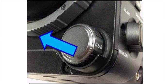
Figure 1
2. Use tweezers to peel off the ND cushion. (See Figure 2.)
NOTE: Discard the ND cushion.
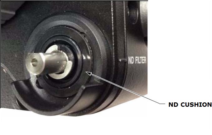
Figure 2
3. Remove the two screws under the removed ND cushion(See Figure 3.)
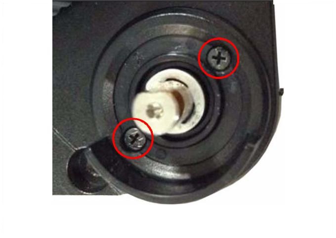
Figure 3
4. Place two new ND washers in the screw holes.(See Figure 4.)
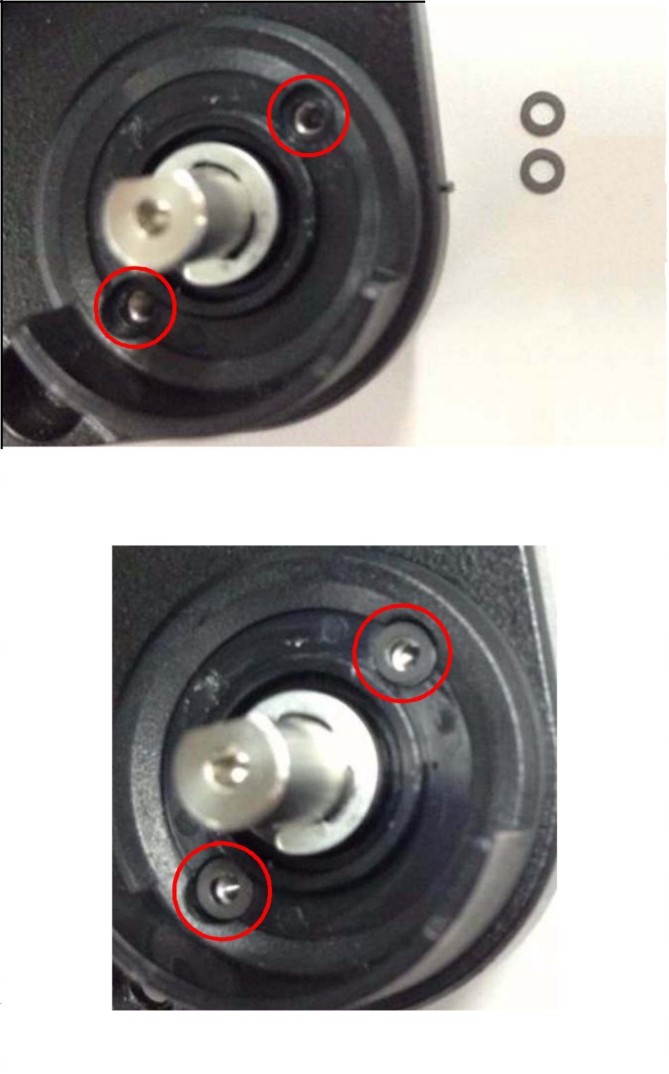
Figure 4
5. Position the new ND click plate as shown in Figure 5, with the C chamfer planes over the screw holes.
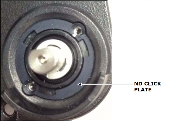
Figure 5
6. Install and tighten the two new +K2×6 screws with a tightening torque of 0.18 N·m. (See Figure 6.)
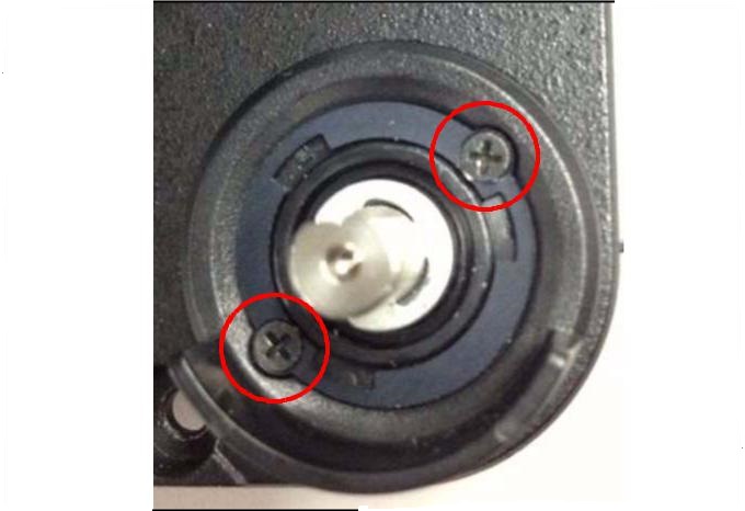
Figure 6
7. Install the new ND dial assembly, fitting the D-cut under the ND dial assembly with the D-cut of the shaft. (See Figure 7.)
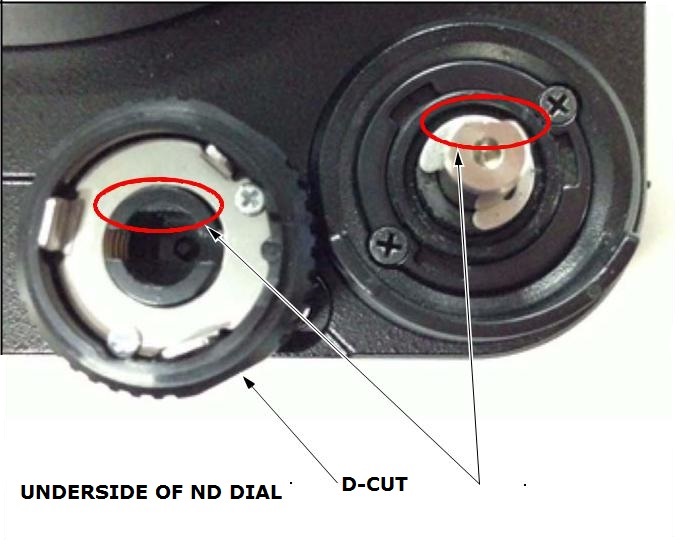
Figure 7
8. Push in the ND dial assembly, confirming that the shaft stops at the clicking position. (See Figure 8.)
NOTE: If the shaft does not stop at the clicking position, the ND dial assembly cannot be pressed deeply.
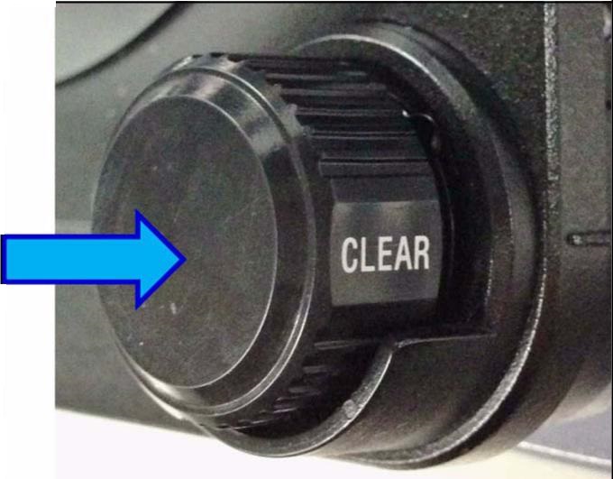
Figure 8
CONFIRMATION
1. Confirm that the ND dial assembly can be pressed deeply to the shaft as shown in Figure 9.
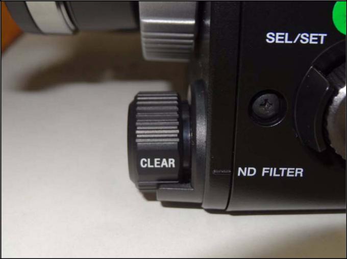
Figure 9
2. Pull and rotate the dial, then release it at the clicking position. The dial is then locked into position and will not be inadvertently rotated out of position. (See Figure 10.)
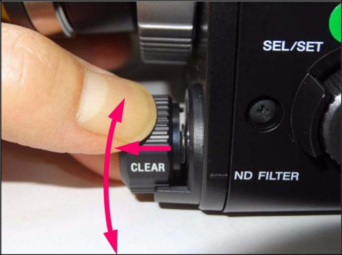
Figure 10